PhotoMachining, Inc.
Material Types
A properly shaped laser beam from a properly chosen laser can drill, cut or mark most materials. Laser micromachining has unique advantages over mechanical machining for extremely tough, brittle, hard or delicate materials. PhotoMachining, Inc. has experience and proprietory technology for many difficult materials.

|
Materials Most popular materials requiring laser processing are:
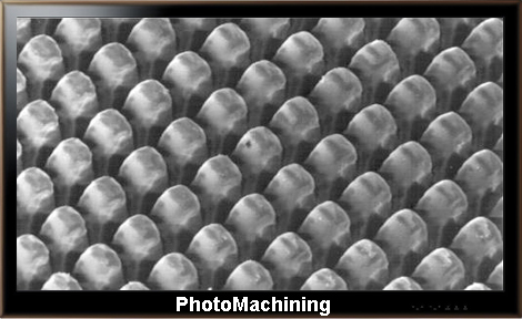
Whenever traditional technology fails, laser-assisted photomachining offers a cost effective and reliable solution. PhotoMachining demonstrates a few real life examples of laser processed parts below on this page. Plastics and Polymers Vias and orifices are easily made in thin walls of plastic parts. Circular vias, squares, ovals or other complicated shapes can be made. Thin plastic films as well as parts several mm in thickness can be laser drilled. Films such as Kapton and Mylar are pretty common materials to be laser machined.
Parylene Another common polymer is parylene. Parylene is a vapor deposited polymer used as a chemical, moisture and dielectric barrier. It is frequently used as a complete covering over complicated topographies. It is used in electronics for space travel and military applications. In the medical market, its uses are diverse and widespread. It offers a level of protection to critical components that is unequaled by any other coating. Parylene is biocompatible, pinhole-free, extremely thin and protects against the effects of fluids and solvents. It is also non-toxic and conforms precisely to substrate contours. It is also used in applications where dry lubricity is important like catheters, syringes and implants. Finally, it adds minimal weight and volume to the finished product. On the ‘negative’ side, parylene is difficult to remove cleanly and precisely once it is applied – traditional methods include thermal (literally burning the material away with a flame or hot iron), mechanical (picks, sanding, scraping) or abrasion using microblasting of fine grit. All of these methods have obvious drawbacks. Fortunately, UV lasers interact extremely well with parylene and can be used to cleanly remove the material down to the substrate surface. This work as been performed with excimer lasers and also with 355 nm and 266 nm DPSS lasers. A very gentle cleaning may be necessary after laser processing in order to clean up minimal debris or possibly carbonization, but the resulting surface is ready for the next step in the processing line.
Metals and Alloys Tough refractory metals and any special alloys can be cut and drilled. Precisely positioned arrays of many vias can be produced with high repeatability.
Ceramics and Glass Vias are easily made in ceramic wafers. Near zero taper along with high density of holes can be achieved. Tough or brittle parts can also be scribed and marked at high speed.
Gem Stones and Diamond Films Lasers are ideal for the processing of both delicate and extremely hard materials. Even diamond, the hardest substance known, can be easily drilled, cut, patterned or planarized using laser machining technology. Diamonds are the hardest natural material and therefore difficult to machine by traditional methods. Since diamonds are simply tetrahedral carbon matrices, they absorb several wavelengths of light quite readily and lasers play a big role in marking and removing occlusions from gemstones and also in patterning CVD (Chemical Vapor Deposited) diamond films. The advantages of CVD diamond include the ability to grow diamond over large areas, the ability to grow on a substrate and the control over the exact properties of the diamond produced. Growth areas of greater than 15 centimeters diameter have been achieved and much larger areas are likely. The 1 micron wavelength couples very well and can be used to cut or drill diamond with very fast speeds and very good edge quality. For gemstones and machine tools, this laser is preferred because of the low cost of processing. In the case of machine tools, slight graphitization on the edges is tolerable since a final dressing step is usually performed. However, when the ultimate in edge quality is needed a UV laser and/or USP laser can be used to cut CVD diamond to exact shapes and sizes with no degradation in edge quality, graphitization, chipping or microcracking. An example is in the manufacturing of heat sinks. One of the challenges to making microelectronics smaller and faster is heat management and CVD diamond is being used to address this problem as diamond, besides being the hardest substance, also has the best thermal conductivity.
CFRP's Carbon fiber reinforced polymers (CFRP’s) are composite materials and therefore they are not homogeneous. In fact, in many cases there are also other fibers in the weave including Kevlar™, aluminum and glass. This can present problems with processing using any method, including lasers. Some of these problems are discussed below. Carbon fiber materials are very expensive, but they display superior performance characteristics to metals especially where superior strength to weight ratio and rigidity are of ultimate importance. The ultimate carbon fiber is a carbon nanotube and these reinforced polymers are several times stronger (and more expensive) than even normal carbon fibers – this material is used in the manufacture of the Lockheed F-35 Lightning II warplane. While the tetrahedral bonding structure of carbon couples well with many wavelengths of light across the spectrum, the epoxies may not respond as well and this heterogeneous mixture presents some challenges. One micron lasers work very well on CFRP’s if used efficiently and if the material is thick enough and the ultimate in edge quality is not needed. Otherwise, UV lasers like 355 nm and 266 nm DPSS lasers (nanosecond pulse lengths) can cut and drill this material with very clean results, although the ultimate thickness is probably on the order of a few hundred microns. Ultra short pulse lasers are finding applications in the processing of composites because they can ablate almost any material and have minimal thermal side effects. This provides a distinct and unique advantage over other methods.
The image above shows a set of 75 micron kerf cuts made in 250 micron thick CFRP using a variety of different lasers, all using galvo scanning and no co-axial gas assist. The parts were not cleaned. While the long wavelength CO₂ laser can cut the material, the edge quality is not very good. The 1 micron fiber laser cuts the material fairly cleanly but leaves a charred edge. A 355 nm UV nanosecond laser leaves a relatively clean edge, but there is still some evidence of local charring. The shorter wavelength 266 nm laser and the shorter pulse width 355 nm laser yield the best edge quality. If microscopic features are required, the best edge quality and lack of residual heat are crucial so that the material will not distort when processing. The most common example of a non-homogeneous fiber composite material is FR4 (Flame Resistant Class 4), which is an epoxy resin embedded with glass fibers. This material is used in printed circuit boards and a host of other electronic and mechanical devices. It has many material advantages such as relatively low cost, mechanical rigidity, excellent dielectric properties and water resistance. It can be drilled with far IR and UV lasers, but the difficulty is in dealing with the non-homogeneity. Glass fibers ablate at a much higher energy density than the epoxy and this higher required energy can sometimes cause problems with the epoxy in the form of undercutting or burning. The real difficulty is that the fibers are not distributed uniformly. For instance, if a large number of holes are required to be drilled, there will be areas where there is no glass, areas where there may be a single glass fiber and areas where there are crossed fibers or even bundles of crossed fibers. All of these cases must be accounted for and in a worst case scenario, the drilling speed will for the panel will be slower because all the holes have to be drilled using the parameters for drilling through fiber bundles rather than pure epoxy. Carbon fiber epoxy material up to several mm in thickness is used in engine components for noise reduction spoilers. This material has some of the same problems as FR4, but the carbon fibers also tend to propagate any heat generated by the laser process, so care must be taken to avoid burning of the epoxy not just around the holes, but also in areas removed from the actual laser processed area. Large numbers of holes with diameters in the range of a millimeter are needed in relatively thick material, so IR lasers are the best choice for this application as the material is thick enough so that internal stresses should not be an issue with the required hole density.
When the material gets very thin and the feature sizes are very small, there are a whole new set of problems that need to be addressed which are also a result of the material non-homogeneity. Internal stresses are relieved when cutting very fine features and distortion can result. This distortion is exacerbated by any residual heat, so in this case USP (Ultra Short Pulse) lasers are definitely an advantage. Internal stresses and physical distortion sometimes allow the material to ‘lift’ during processing, and this causes a shadowing effect which can affect completion of a through cut. For very thin material it is sometimes helpful to epoxy the material to a flat substrate, preferably transparent to the laser wavelength used for processing. This prevents localized distortion while the laser is being used. After dissolving the glue, internal stresses are relieved in a much more uniform fashion when removing the material from the carrier.
The image above shows picosecond UV laser processing of fine ribs. These ribs are only 30 microns in width and are separated by about 200 microns. The size of the laser beam on target was about 25 microns compared to a material thickness of 250 microns giving an aspect ratio of about 10:1. The ribs are cut cleanly and exhibit no distortion or obvious heat effects. In summary, CFRP’s are available in a variety of different thicknesses and in general are easily processed using a number of different lasers, depending on the requirements of the application. Short pulse, and especially short pulse UV lasers can be used to make intricate structures with no apparent heat distortion. |
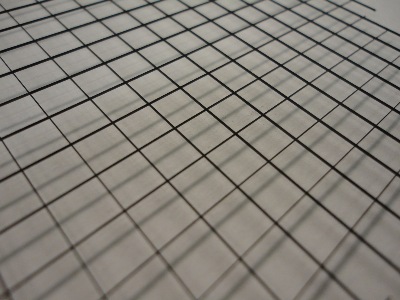
 Fragment of an array of 1000 vias 75 microns in diameter in 15 microns thick plastic wall
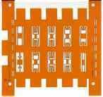 Complex pattern cut in 50 microns thick Kapton film using 248 Excimer laser
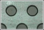
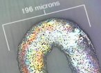
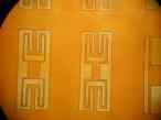 Close up of one of the cuts in the sample shown to the left.
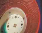
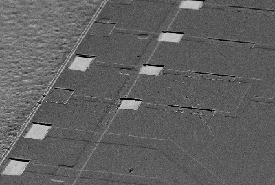 The figure to the left shows laser removal of parylene from coated IC pads.
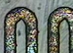
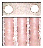
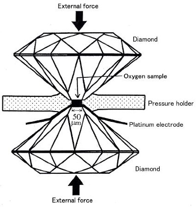 Diamond "Anvils" with laser drilled holes.
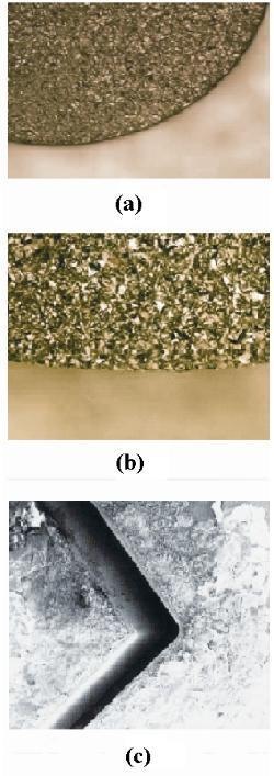
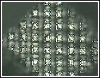
 Free standing diamond screen.
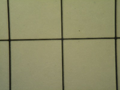 Close up of free standing diamond screen.
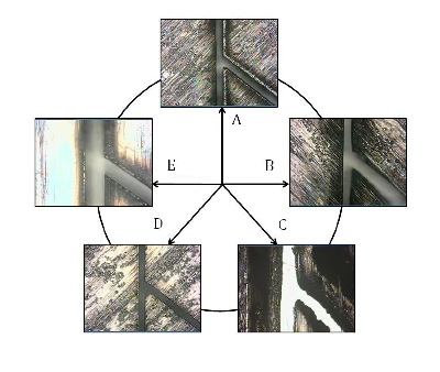 Various Lasers Used to Cut Thin CFRP Material
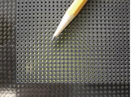 Laser Drilled Carbon Fiber Epoxy Panel Compared to a Pencil
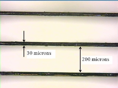 High Resolution Features in Thin CFRP Material